Schematic diagram of a basic Step-Up converter integrated in a

Download scientific diagram | Schematic diagram of a basic Step-Up converter integrated in a photovoltaic generator. PV is a photovoltaic panel, PWM is the Pulse Width Modulator. C1, C2, Rp, Rs, L1, D1 and M1 are the discrete elements constituting the electronic circuit (see the text). from publication: Basic MOSFET Based vs Couple-coils Boost Converters for Photovoltaic Generators | Considering the optimization of a photovoltaic system, several studies show the advantage in the choice of a distributed structure. For such structures small power converters such as the boosts and buck converters appear as most appropriate. We have analysed the efficiency of | MOSFET, Photovoltaics and Boost | ResearchGate, the professional network for scientists.
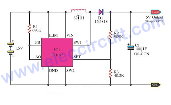
Most DC to DC Converter Step Up Voltage Circuits using LT1073

Step-down Converter - an overview
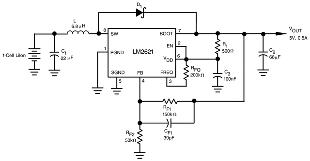
LM2621 data sheet, product information and support
A new extended single-switch high gain DC–DC boost converter for

3 to 12 volts step up DC converter using MAX668 ic

Current Paths in Step-up DC-DC Converters

DC-DC boost converter circuit

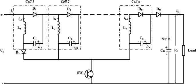
Non-isolated high step-up DC/DC converters – An overview
Technologies, Free Full-Text

DC to DC Buck Converter Tutorial & Diagram

Micropower 600kHz Fixed-Frequency DC/DC Converters Step Up from a

Circuit diagram of the integrated buck/ buck converter.

Circuit diagram of High Step up dc-dc converter

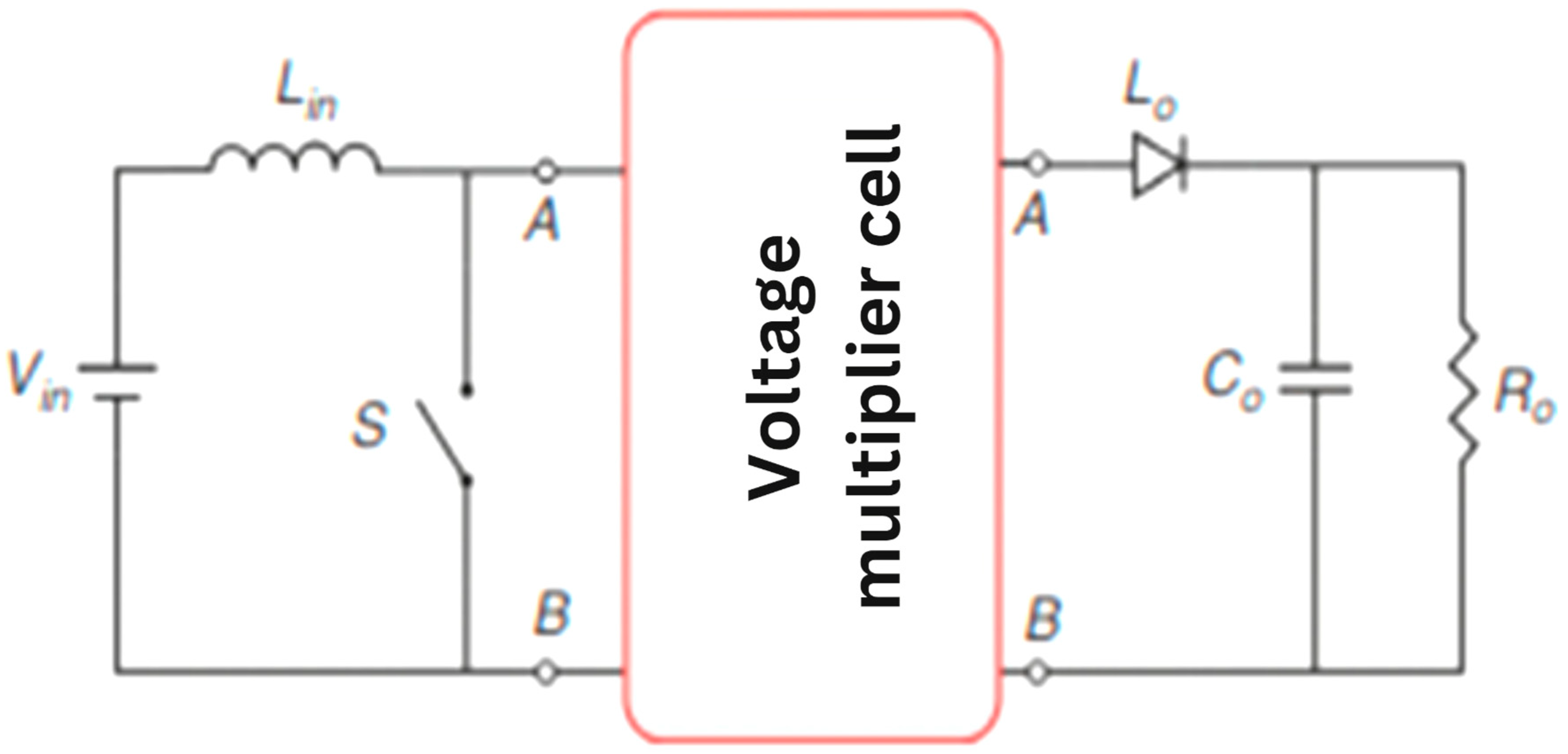
Block diagram of the proposed step-up converter.